バックナンバーはこちら。
https://www.simulationroom999.com/blog/model-based-of-minimum-2-backnumber/
はじめに
「OpenModelicaで作ったFMUをFMILibraryで制御する」
までの、おおよそのプランを提示。
使用するモデルは以前動作確認したDCモータモデルだが、
PID制御器を付けてオープンループ制御からクローズループ制御にしたものにする予定。
登場人物
博識フクロウのフクさん

イラストACにて公開の「kino_k」さんのイラストを使用しています。
https://www.ac-illust.com/main/profile.php?id=iKciwKA9&area=1
エンジニア歴8年の太郎くん

イラストACにて公開の「しのみ」さんのイラストを使用しています。
https://www.ac-illust.com/main/profile.php?id=uCKphAW2&area=1
DCモータモデル変更
まずはDCモータモデルの変更からかな?
そうだね。
PID制御器を追加する。
PID制御を作ることになるのか・・・。
まぁ一応どういうものかは知ってはいるけど、
Modelicaで書くとなるとイメージ湧かないな・・・。
PID制御器は最初からライブラリとして用意されてるよ。
ModelicaライブラリのPID制御器
え?
そうなの?
だったら、それをそのまま繋げばOKじゃん!
そうだね。
まぁ実際に使うのはLimPIDというモデルになる。
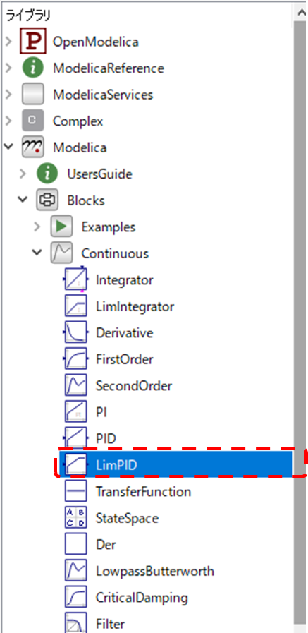
Modelicaライブラリのどこにあるのかな?
ライブラリブラウザで
Modelica→Blocks→Continuous
で辿って行った先にLimPIDってのがあるんで、それを使う。
PID制御器のパラメータは?
PID制御器と言うと、各種パラメータを決める必要があると思うんだけど?
そうだね。
それに今回使用するPID制御器のパラメータは
\(P\)ゲイン、\(I\)ゲイン、\(D\)ゲインではなく、
\(K_p、T_i、T_d\)を指定するタイプだ。
\(T_i\)?
\(T_d\)?
まぁ通常のPID制御の式を変形して、
時間をパラメータとするようにしたPIDだな。
以下に一般的なPID制御の数式と時間パラメータに変更した式を併記しよう。
$$ C(s)=K_p + \frac{k_i}{s} + K_d s = K_p(1+\frac{1}{T_i s}+T_d s) $$
まぁ今回はPID制御のパラメータは本筋ではないので、
\(K_p=0.75\)
\(T_i=0.03\)
\(T_d=0.075\)
を設定しておこう。
そんなに大外れなパラメータにはならないはずだ。
そういうことならそれを設定しておこう。
出来上がったモデル
そして出来上がってモデルがこれになる。
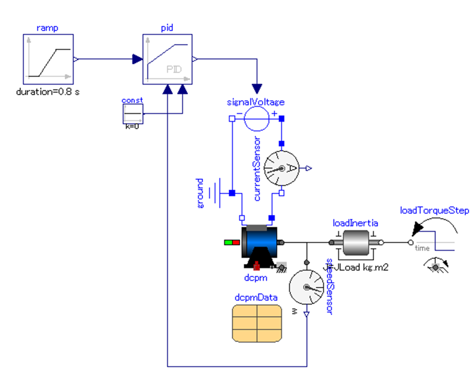
RampとsignalVoltageの間にPID制御器が入った感じだねー。
あとは、電流センサと角速度センサも追加されてる感じか。
そうだね。
角速度センサは角速度フィードバックをするために追加。
電流センサは制御としては使わないが、モータの内部状態を見るには重要なパラメータなんで、
一応付けておいたって感じだ。
まとめ
まとめだよ。
- 以前使ったDCモータモデルにPID制御器を付けた。
- PID制御器はModelicaライブラリに最初から存在。
- 実際にはLimPID。
- パラメータはKp、Ki、KdではなくKp、Ti、Tdな点に注意。
- とりあえず、クローズループ(PID)制御のDCモータモデルが出来た。(つもり)
バックナンバーはこちら。

コメント